
Seismic Anchorage for Mechanical Equipment in California: What Permit Plans Should Show
Mechanical equipment is essential to a building’s operation, but it can become a significant hazard if it is not properly supported and anchored. Air-handling units, pumps, boilers, fans, water heaters, electrical equipment, and other components may shift, overturn, or damage connected systems during an earthquake.
Proper seismic anchorage for mechanical equipment in California requires more than selecting a few bolts. The design must consider the equipment, its location, the supporting structure, vibration isolation, connections, and the forces expected at the project site.
Coordinating these items before permit submittal helps reduce plan-check comments, equipment substitutions, and unsafe field modifications.
Identify the Equipment Being Installed
The design should begin with accurate information about the actual equipment. Preliminary schedules can help establish a layout, but final anchorage calculations normally depend on the selected manufacturer and model.
The engineering team may need:
- Equipment dimensions and operating weight
- Center-of-gravity location when available
- Base-frame or mounting-hole configuration
- Manufacturer anchorage requirements
- Equipment certification information
- Vibration-isolator details
- Service and maintenance clearances
- Connected duct, pipe, conduit, and cable locations
- Support-frame or housekeeping-pad dimensions
Equipment substitutions should be reviewed before installation. A replacement unit may have the same capacity as the specified equipment while having a different weight, footprint, center of gravity, or mounting arrangement.
Determine the Equipment’s Seismic Demand
The force applied to a nonstructural component is not based solely on its weight. The anchorage design may also depend on the building’s seismic design category, equipment location, building height, component importance, attachment configuration, and flexibility.
Equipment installed at an upper floor or on a roof can experience different demands than similar equipment located at grade. Life-safety equipment and components that must continue operating after an earthquake may also require additional consideration.
The structural engineer should establish the applicable design criteria and clearly identify the forces used to design the support and anchorage system.
Provide a Continuous Load Path
Anchorage is only effective when seismic forces can travel through a complete load path into the building structure. The engineer must evaluate more than the connection between the equipment and its immediate support.
A typical load path may include:
- Equipment casing or base frame
- Manufacturer mounting points
- Bolts, clips, brackets, or welded connections
- Vibration isolators or restraint assemblies
- Structural support frame
- Housekeeping pad or building framing
- Primary floor or roof structure
A strong anchor installed into an inadequately reinforced pad does not create a reliable connection. Similarly, a heavy unit fastened only to roof sheathing, thin metal deck, or a nonstructural partition may not have a complete load path.
Permit details should show how every part of the assembly transfers forces to structural members.
Coordinate Vibration Isolation and Seismic Restraint
Mechanical equipment often uses vibration isolators to reduce noise and movement during normal operation. However, flexible isolators allow movement and cannot automatically provide the restraint required during an earthquake.
The mechanical and structural engineers should coordinate:
- Isolator type and height
- Equipment operating movement
- Seismic snubbers or restraint devices
- Required clearances around restraints
- Attachment of isolators to the equipment and support
- Lateral and vertical restraint requirements
- Flexible connections for ducts, pipes, and electrical services
The seismic-restraint system must protect the equipment without preventing the vibration-isolation system from functioning properly during normal use.
Check the Supporting Structure
Mechanical-equipment anchorage cannot be designed independently from the building structure. The floor, roof, wall, or support frame receiving the equipment forces must be capable of resisting them.
For existing buildings, field verification may be needed to confirm:
- Concrete slab or housekeeping-pad thickness
- Reinforcement information
- Roof-framing sizes and direction
- Steel-beam or joist locations
- Wood-framing sizes and spacing
- Existing penetrations and nearby anchors
- Edge distances and available embedment
- Corrosion, cracking, deterioration, or prior alterations
Existing drawings are helpful, but they should be compared with visible field conditions. If the required structural information is unavailable, limited investigation may be necessary before the final anchorage details are issued.
Coordinate Housekeeping Pads and Support Frames
Housekeeping pads elevate equipment above the floor and can provide a level installation surface. However, a pad must be properly connected to the supporting slab if it is expected to transfer seismic forces.
The design may need to define:
- Pad dimensions and concrete strength
- Reinforcement and dowels
- Connection to the existing slab
- Anchor type and embedment
- Minimum spacing and edge distances
- Required surface preparation
- Equipment-base grouting
Support frames should also be designed for equipment weight and seismic forces. Frame bracing, member connections, welding, bolting, and attachment to the building structure should be shown clearly.
Protect Connected Building Systems
Even when equipment remains anchored, connected services can be damaged if they cannot accommodate movement. Rigid piping, conduit, ducts, and control connections may transfer forces into the equipment or fail near connection points.
The coordinated design should consider flexible connectors, pipe bracing, duct supports, conduit restraint, and appropriate clearances. Fire-protection piping, fuel-gas piping, refrigerant lines, and emergency electrical systems may require particular attention because failure could create additional hazards or interrupt essential operations.
GDI’s MEP engineering services can help coordinate these systems with the structural support and anchorage requirements.
Show the Anchorage Clearly on Permit Plans
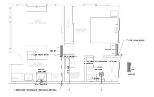
Permit drawings should provide enough information for the plan reviewer and contractor to understand the proposed installation. Referring only to “manufacturer requirements” may not be sufficient when the connection to the building structure requires engineering.
A coordinated submittal commonly includes:
- Equipment schedule with manufacturer, model, and weight
- Equipment location and orientation
- Applicable seismic-design criteria
- Anchorage calculations
- Anchor type, diameter, quantity, and embedment
- Minimum spacing and edge distances
- Support-frame and housekeeping-pad details
- Connection to the primary building structure
- Vibration-isolation and seismic-restraint details
- Special-inspection requirements when applicable
California’s 2025 Building Standards Code became effective statewide on January 1, 2026, although local amendments and project-specific requirements must also be confirmed with the authority having jurisdiction. California Department of General Services
Verify the Installation in the Field
The final installation should match the approved details. Common field issues include incorrect anchor types, insufficient embedment, misplaced bolts, conflicts with reinforcement, missing brackets, and equipment substitutions.
Early coordination among the engineer, supplier, and contractor can prevent these problems. When field conditions differ from the approved plans, the engineer should review the condition before the contractor makes an improvised modification.
Proper seismic anchorage for mechanical equipment in California protects occupants, equipment, and essential building systems. GDI Engineering can evaluate the supporting structure, prepare anchorage calculations and details, and coordinate mechanical and structural permit documents.
Contact GDI Engineering to share the equipment information, building address, plans, and available site photographs for review.