Top Challenges in MEP Coordination and How to Overcome Them
Introduction
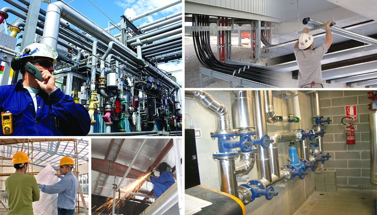
Modern buildings rely heavily on mechanical, electrical, and plumbing (MEP) systems to function safely and efficiently. But behind every working HVAC unit or lighting circuit is a maze of pipes, wires, and ducts that must fit precisely within the building’s structure.
That’s where MEP coordination comes in—and it’s no small feat. From design complexities to conflicting trades, MEP design challenges can quickly derail schedules and inflate costs. But with the right planning and expertise, these challenges are completely manageable.
Let’s explore the most common issues MEP engineering firms face—and how to overcome them.
Why MEP Coordination Is So Critical
Before diving into the challenges, it’s important to understand what’s at stake.
MEP design is all about ensuring comfort, functionality, and safety. But these systems aren’t installed in a vacuum—they must integrate with structural elements, architectural features, and other disciplines. Coordination is what ensures everything fits, works, and meets code without conflict or costly rework.
At GDI Engineering, we approach every project with a collaborative mindset, aligning all disciplines early to avoid downstream issues.
10 Common Challenges in MEP Coordination
1. Clashes Between Systems
One of the most frustrating issues in MEP coordination is spatial conflict. A duct hits a beam. A plumbing stack interferes with fire protection. Without early clash detection, these problems cause major delays and change orders.
2. Constantly Changing Codes
Building codes and energy regulations evolve constantly. Ensuring your designs are up to date—and code-compliant across all jurisdictions—is an ongoing challenge.
3. Aggressive Project Timelines
Tight deadlines often leave little room for proper coordination. When MEP teams aren’t brought in early, they’re forced to fit systems into designs that are already locked in.
4. Budget Constraints
Clients want high-efficiency systems and sustainable design—but sometimes without the budget to match. Striking the right balance between performance and cost requires deep expertise.
5. Communication Breakdowns
MEP coordination requires constant collaboration across architects, engineers, contractors, and trades. If communication breaks down, errors creep in and revisions pile up.
6. Inconsistent or Outdated Models
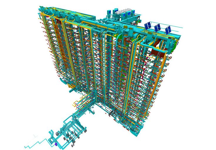
Working from outdated drawings or uncoordinated 2D plans creates confusion. Without a reliable 3D model or BIM process, it’s hard to spot issues before they become field problems.
7. Challenges in Renovations and Retrofits
Older buildings often lack accurate as-built documentation. This makes it difficult to plan modern systems without running into unknown obstacles.
8. Poor Maintenance Access Planning
Even when systems are installed correctly, poor planning for future maintenance can cause long-term headaches. Tight spaces and blocked access panels aren’t just annoying—they’re expensive to fix later.
9. Shortage of Skilled Talent
Finding professionals with deep experience in BIM coordination, energy modeling, and integrated MEP design is getting harder. The talent gap adds risk to projects.
10. Sustainability Pressures
Green building certifications and energy mandates are becoming the norm. But integrating energy-efficient systems adds complexity and increases the need for precise coordination.
How to Solve These Challenges
Solving MEP coordination issues isn’t about working harder—it’s about working smarter. Here’s how successful MEP firms (like ours) get it done:
Start Early
Bring MEP engineers into the design process from the start. Early input means fewer changes later and systems that integrate cleanly with architectural and structural elements.
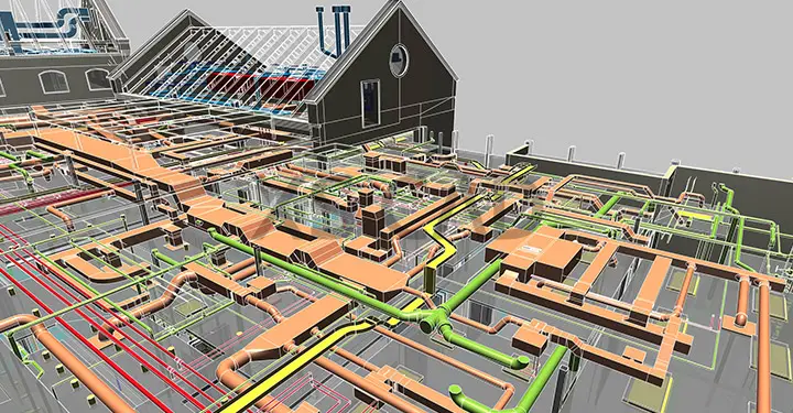
Leverage BIM and 3D Modeling
Invest in detailed, up-to-date 3D models. Run regular clash detection. Keep every stakeholder working from the same set of plans. This is the cornerstone of good coordination.
Communicate Often—and Clearly
Schedule regular coordination meetings. Use cloud platforms to share models and markups in real time. Make sure every team is aligned on timelines, changes, and responsibilities.
Embrace Prefabrication
Where possible, use prefabricated MEP assemblies. These improve quality control, reduce field labor, and minimize spatial conflicts.
Value Engineer Thoughtfully
Look for ways to reduce cost without sacrificing performance—such as rerouting systems, changing equipment, or switching to modular options. Always consider lifecycle cost, not just initial spend.
Use Accurate As-Built Data
For retrofits, gather precise field data using 3D scanning or manual surveys. The more you know upfront, the fewer surprises later.
Prioritize Maintenance Access
Design with the long term in mind. Ensure all systems are accessible for servicing, inspection, and eventual replacement. It’s an investment that pays off in reliability.
Stay Updated on Codes and Trends
Keep your team trained and informed. Know the latest code changes, energy requirements, and industry best practices so your designs don’t fall behind.
Conclusion
MEP engineering firms are central to successful building design. Their ability to coordinate mechanical, electrical, and plumbing systems determines efficiency, cost, and long-term performance. By engaging early, using advanced tools like BIM, and applying industry best practices, projects avoid costly rework and delays.
Looking for expert support? Explore our MEP engineering services and discover how GDI Engineering can help your project succeed.