Building Dreams, Crafting Realities

+1 346-250-7210

info@gdiengdesign.com

Structural Steel Detailing Services
13, Aug 2026
Complete Guide to Structural Steel Detailing Services for Modern Construction Projects

Structural steel is widely used in commercial, industrial, institutional, warehouse, and other building projects because it provides strength, flexibility, and the ability to create large open spaces. 

However, steel construction requires more than a structural concept.

The design must be translated into accurate fabrication and erection information so that beams, columns, braces, plates, bolts, and connections can be manufactured and assembled correctly.


This is where professional Structural Steel Detailing Services become extremely important.

Steel detailing connects the structural design to fabrication and construction.

A good detailing process helps reduce errors, improve coordination, and provide fabricators and erectors with the information they need to build the structure.

What Is Structural Steel Detailing?

Structural steel detailing is the process of creating detailed drawings and models that show how steel components should be fabricated and assembled.

These documents may include:


  • Shop drawings
  • Erection drawings
  • Connection details
  • Member dimensions

  • Hole locations
  • Bolt information

  • Weld information

  • Plate sizes

  • Material specifications

  • Assembly marks

Structural design drawings show the overall engineering intent.


Detailing takes that information and develops it into fabrication-level documentation.

The detailer must understand structural drawings, specifications, connection requirements, and fabrication practices.

Structural Steel Detailing Services and Construction Accuracy

Accuracy is critical in steel construction.

A small dimensional error can create significant problems because steel components are often fabricated off-site.

When a beam arrives on the job site with incorrect holes or dimensions, it may not fit.

Field modifications can be expensive and may require engineering review.

Detailed coordination helps reduce these problems.

The goal is to identify discrepancies before fabrication begins.

BIM Steel Structure Design Services

BIM Steel Structure Design Services have changed the way steel projects are coordinated.


Three-dimensional models allow the team to visualize the entire steel frame before fabrication.

Beams, columns, braces, connections, stairs, and other components can be represented within the model.


This helps identify conflicts and dimensional problems.

For example, a connection plate may interfere with another beam.

A brace may conflict with architectural openings.

A steel member may interfere with mechanical ductwork.

BIM makes these issues easier to identify before construction.

Shop Drawings

Shop drawings are among the most important deliverables in steel detailing.

They provide fabrication information for individual members or assemblies.

A shop drawing may show:

  • Member length

  • Material grade

  • Connection plates

  • Bolt holes

  • Welds

  • Coping

  • Cut dimensions

  • Assembly information

Fabricators use these drawings to manufacture the steel.

Because of this, the drawings must be clear and consistent.

Shop drawings are typically reviewed as part of the construction process.

They should reflect the structural design intent while also incorporating practical fabrication requirements.


Erection Drawings

Erection drawings show how steel members are assembled on the job site.

They may identify:

  • Member marks

  • Locations

  • Elevations

  • Grid lines

  • Connection points

  • Installation sequence

  • information

Erectors use these drawings to understand where each piece belongs.

Clear erection drawings can improve field productivity and reduce confusion.

Steel Building Design Services USA

Professional Steel Building Design Services USA can include engineering for complete structural steel systems.

Engineers may design:

  • Beams

  • Columns

  • Braced frames

  • Moment frames

  • Joists

  • Trusses

  • Connections

  • Foundations

  • Equipment supports

  • Platforms

  • Canopies

The structural design must account for gravity loads and lateral loads such as wind and seismic forces.

The engineer determines the required member sizes and structural system.

Steel detailing then translates that engineering design into fabrication information.

Strong coordination between engineering and detailing helps the project move more smoothly.

Structural Connections


Connections are a critical part of steel structures.

They transfer forces from one member to another.

Common connection components include:

  • Bolts

  • Welds

  • Shear tabs

  • End plates

  • Base plates

  • Gusset plates

  • Clip angles

The connection type depends on the forces being transferred and the structural system.

Some projects use standard connection requirements.

Others require project-specific connection design.

Detailers must represent these connections accurately.

Coordination With Architecture

Steel framing needs to support the building while also fitting within the architectural design.

Columns should align with walls where possible.

Beams must coordinate with floor and ceiling elevations.

Openings may be required for doors, windows, and building services.

Architectural changes can affect the structural steel.

If an opening changes size or location, nearby members may need to change.


Good coordination between the structural team and architect reduces redesign.

Coordination With MEP Systems

Mechanical, electrical, and plumbing systems often pass through or around steel framing.

Large ductwork may conflict with beams.

Pipes and conduits may require penetrations or routing adjustments.

Mechanical equipment may require steel supports.

BIM can help identify these conflicts.

It is much easier to reroute a duct in a digital model than to modify a fabricated steel beam in the field.

Pre-Engineered Steel Building Design Services

Pre-Engineered Steel Building Design Services are commonly used for warehouses, industrial buildings, storage facilities, agricultural buildings, and other structures requiring large open areas.

Pre-engineered building systems typically use repetitive framing and optimized steel members.

The building manufacturer may provide the primary metal building system, but other engineering may still be required.


Examples include:

  • Foundations

  • Equipment supports

  • Mezzanines

  • Canopies

  • Interior framing

  • Openings

  • Connection interfaces

Coordination between the metal building supplier and project structural engineer is important.


Foundation reactions from the building manufacturer must be incorporated into the foundation design.

Fabrication Efficiency

Good detailing can improve fabrication efficiency.

Standardized connections and clearly organized shop drawings help fabricators work more effectively.

Accurate material lists can also help reduce waste.

When details are incomplete or inconsistent, fabricators may need to submit RFIs or delay production.

Resolving these issues before fabrication improves schedule reliability.


Reducing Field Changes

One of the major benefits of detailed steel coordination is reducing field modification.

Field welding, drilling, or cutting can be expensive and may affect structural performance.

Changes should not be made casually.

The engineering team may need to review modifications.

Good detailing attempts to eliminate these situations by identifying problems before fabrication.

Steel Detailing for Renovation Projects

Existing buildings can also require steel detailing.

Renovations may add:

  • New beams

  • Reinforcement

  • Equipment frames

  • Stair framing

  • Canopies

  • Roof supports

  • Mezzanines

Existing conditions can create challenges because dimensions may not match original drawings.

Field measurements may be important.

Connections must be coordinated with existing structure.

Quality Control


Steel detailing should include a quality-control process.

Drawings and models should be checked for:

  • Dimensions

  • Member sizes

  • Connection details

  • Alignment

  • Material information
  • Drawing consistency
  • Revision coordination

Changes during design should also be tracked carefully.

Using outdated drawings can lead to fabrication errors.

Revision management is therefore an important part of the detailing process.

Conclusion

Structural steel construction depends on precision.

Professional Structural Steel Detailing Services help convert engineering design into accurate fabrication and erection information.

Modern BIM Steel Structure Design Services improve visualization and clash detection, allowing teams to identify conflicts before fabrication begins.

Professional Steel Building Design Services USA provide the engineering foundation for safe and efficient steel structures, while Pre-Engineered Steel Building Design Services support specialized metal building systems and their foundations and interfaces.

When engineering, detailing, BIM, fabrication, and construction are properly coordinated, structural steel projects can move faster, reduce field changes, and achieve a much higher level of accuracy.


BIM wood structure design
13, Aug 2026
BIM Wood Structure Design Services Improving Accuracy in Timber Construction Projects

Wood construction has evolved significantly in recent years.

Traditional wood framing continues to be widely used in residential and light-commercial construction, while mass timber systems such as cross-laminated timber and glued-laminated timber are creating new opportunities for larger and more complex buildings.

As timber projects become more sophisticated, digital coordination becomes increasingly important.

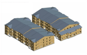
Professional BIM Wood Structure Design Services can improve accuracy by allowing engineers, architects, contractors, and fabricators to coordinate structural components in a three-dimensional environment before construction begins.

This is particularly valuable for mass timber and exposed timber buildings where structural components often serve both engineering and architectural purposes.


Modern Wood Structural Systems

Wood structures can use several different framing systems.

Traditional construction may include:

  • Wood studs

  • Floor joists

  • Roof rafters

  • Engineered wood I-joists

  • Laminated veneer
    lumber

  • Wood trusses

Heavier timber construction may include:


  • Glulam beams

  • Heavy timber columns

  • Cross-laminated timber
    panels

  • Mass plywood panels

  • Timber trusses

Each system has different design, connection, and fabrication requirements.

Professional Wood Structure Engineering Services help determine member sizes, load paths, connections, and lateral-force-resisting systems.

What Is BIM for Wood
Structures?


Building Information Modeling creates a digital representation of the building.

For timber projects, the structural model may include beams, columns, wall panels, floor panels, roof framing, connections, and openings.

Unlike traditional two-dimensional drawings, BIM allows the project team to understand how these components interact in three-dimensional space.


This is useful because timber construction can involve complex geometry and prefabricated elements.


A panel fabricated incorrectly may be difficult to modify on site.

Digital coordination reduces that risk.

Improving Accuracy Through BIM

One of the largest benefits of BIM Wood Structure Design Services is dimensional coordination.

The structural model can be coordinated with architectural and MEP models.

This helps ensure that:

  • Beams align correctly

  • Columns fit within walls

  • Openings are properly located

  • Mechanical penetrations are coordinated

  • Floor elevations match

  • Connections have
    adequate space

These issues can be difficult to identify on separate two-dimensional drawings.

The 3D model makes them much easier to visualize.

Mass Timber Design Services

Mass Timber Design Services involve engineering large engineered wood elements that may replace conventional steel or concrete components.

Mass timber can include:

  • CLT floor and wall panels
  • Glulam beams and columns
  • Heavy timber framing

  • Engineered timber diaphragms

These systems can provide structural capacity while also creating warm, exposed architectural interiors.

Because many components are prefabricated, accurate design information is essential.

Panel dimensions, connection locations, penetrations, and tolerances should be coordinated before manufacturing.

BIM helps support this process.


Cross-Laminated Timber

Cross-laminated timber is made from layers of wood arranged in alternating directions and bonded together.

CLT panels can be used for floors, roofs, and walls.

Panels may be manufactured off-site and delivered ready for installation.

Openings for stairs, elevators, ducts, and services can be coordinated digitally.

If these openings are not identified before fabrication, changes may be difficult or expensive.

This is one reason BIM is especially useful for CLT construction.

Glulam Beams and Columns

Glue-laminated timber allows large structural members to be manufactured from smaller wood laminations.

Glulam beams can span substantial distances and can also be shaped for architectural purposes.

Connections between glulam members require careful design.


Steel plates, bolts, dowels, screws, and proprietary connectors may be used.

BIM can help the team visualize these connections and confirm clearances.

This is particularly important when timber remains exposed because connections may also affect architectural appearance.

Timber Frame Structural Engineering Services

Professional Timber Frame Structural Engineering Services evaluate how loads move through a timber building.


The engineer considers:

  • Floor loads

  • Roof loads

  • Snow loads where applicable

  • Wind loads

  • Seismic forces

  • Member spans
  • Connections

  • Foundations

  • Lateral stability

Timber buildings require a complete load path just like steel or concrete buildings.

Gravity loads must travel through beams and columns into the foundation.

Wind and seismic forces must be resisted by shear walls, frames, diaphragms, or other structural systems.

Connections are especially important because they transfer forces between timber components.


Connection Design


Connection design is one of the most important parts of timber engineering.

Wood behaves differently from steel and concrete.

The engineer must consider grain direction, fastener spacing, edge distances, bearing, splitting, and other material behavior.

Connections may include:

  • Bolts

  • Screws

  • Nails

  • Steel plates
  • Hangers

  • Hold-downs

  • Custom fabricated connectors

BIM can help represent connection geometry and detect conflicts.

For exposed timber buildings, visual appearance may also be important.

Hidden or concealed connections may be preferred in some areas.


Engineering and architecture should coordinate these decisions early.

MEP Coordination in Timber Buildings

Mechanical and electrical systems can be challenging in exposed timber buildings because there may be fewer concealed spaces.

Ductwork, sprinkler piping, conduits, and plumbing must be coordinated carefully.

Penetrations through structural timber cannot simply be added anywhere.

Large openings can reduce the capacity of beams or panels.

The engineering team should review penetrations before fabrication.

BIM allows the MEP team to model equipment and routing so that structural openings can be planned properly.

This can reduce field drilling and cutting.

Prefabrication and Digital Manufacturing

Mass timber construction relies heavily on prefabrication.

Computer-controlled equipment can cut panels and members with high precision.

This creates an opportunity for efficient construction but also places more responsibility on the design model.

Incorrect dimensions can be reproduced very accurately—which means the model must be correct.

Digital coordination and quality control are therefore critical.

BIM information may support shop drawings, fabrication models, and installation planning.

Construction Speed

One advantage of mass timber construction can be faster structural erection.

Prefabricated panels and members arrive ready for installation.

However, this benefit depends on accurate planning.

If components do not fit, construction may slow quickly.

Good BIM coordination helps maximize the benefits of prefabrication.

The contractor can better understand installation sequence and access.

Crane planning and material staging may also benefit from digital models.

Sustainability and Timber Construction

Timber is often discussed as part of sustainable building strategies.


Wood is a renewable material when sourced responsibly.

Mass timber may also provide opportunities to reduce reliance on other structural materials in appropriate applications.

However, sustainability involves more than material selection.

The building must still be durable, efficient, safe, and maintainable.

Good structural engineering helps ensure the timber system performs properly over its service life.

Digital coordination can also help reduce material waste and unnecessary field modifications.

Moisture and Durability

Wood structures need protection from moisture.

Design and construction should consider water exposure, drainage, building envelope details, and temporary construction conditions.

Mass timber components can be particularly sensitive during construction if exposed to prolonged moisture.

The project team should plan storage, installation, and protection.

Structural details should avoid locations where water can become trapped.

BIM can help coordinate architectural and structural details that affect durability.

Fire Design

Modern timber buildings must also address fire-resistance requirements.

Heavy timber members can develop a protective char layer when exposed to fire, and engineers may account for this behavior depending on the system and applicable code.

Some assemblies may require additional fire protection.

Penetrations and connections should also be coordinated with fire-rated construction.

Because code requirements can vary depending on building size, occupancy, and construction type, timber projects should involve engineers familiar with the applicable standards.

BIM Quality
Control

The value of BIM depends on accurate information.

Models should be reviewed regularly for:

  • Member sizes

  • Coordinates

  • Openings

  • Connections

  • Levels

  • Structural grids

  • Architectural alignment

  • MEP conflicts

Revision control is important.

When architectural plans change, the structural model should be updated accordingly.

Otherwise, fabrication information may become inconsistent.

Conclusion

Timber construction is becoming increasingly sophisticated, and digital coordination is helping project teams manage that complexity.

Professional BIM Wood Structure Design Services improve accuracy by allowing structural components, architectural features, and building systems to be coordinated before fabrication and construction.

Experienced Wood Structure Engineering Services provide the structural calculations and design needed for safe timber buildings.

Specialized Mass Timber Design Services support advanced systems such as CLT and glulam, while Timber Frame Structural Engineering Services help develop reliable load paths, connections, and framing systems.

By combining structural engineering with BIM, timber projects can benefit from better coordination, reduced field conflicts, improved prefabrication, and more predictable construction.


Commercial Steel Framing Structure
6, Aug 2026
How Steel Framing Design Improves the Strength and Performance of Commercial Buildings


Introduction:The Unmatched Backbone of Modern Commercial Architecture

Structural steel remains the primary material of choice for high-rise commercial office towers, industrial distribution centers, sports arenas, and large commercial retail structures. Its high tensile and compressive strength, combined with ductility and structural predictability, enables architects and structural engineers to push physical limits with column-free spans and towering vertical profiles.

However,realizingsteel’sfullstructuralpotentialrequiresmeticulousengineering.Frominitial steel framing design for commercial buildings to complex structural steel connection design and legacy updates via steel retrofit engineering services, structural design determines a building’s resilience against wind, gravity, and seismicforces.

Apex Engineering Solutions | Technical Blog Series

Principles of High-Performance Commercial Steel Framing Design

Engineering a steel building frame involves balancing lateral force-resisting systems (LFRS) with gravity load paths. Structural engineers utilize three main steel framing configurations:

• Moment-Resisting Frames (MRF): Rigid beam-to-column connections that absorb lateral loads through member bending, eliminating the need for diagonal bracing and allowing uninterrupted curtain wall glazing and open interior floor plans.

• Braced Frames (CBF & EBF): Concentrically or eccentrically braced truss configurations that provide exceptional lateral stiffness against high wind and earthquake loads at lower overall steel weight.

• Dual Systems: Combined moment frames and concrete core shear walls optimized for super-tall commercial developments.

The Critical Science of Structural Steel Connection Design

A steel frame is only as strong as its connections. Minor miscalculations at beam-column intersections can lead to structural localized yielding or sudden connection failure under extreme loading events. Expert structural steel connection design focuses on three critical joinery types:

• Shear Connections (Simple Connections): Designed to transfer vertical gravity shear loads using clip angles or shear tabs, allowing rotational flexibility.

• Moment Connections (Fully Restrained): Engineered to transfer high bending moments using full-penetration welds and heavy flange cover plates, maintaining rigid 90-degree angles during lateral loading.

• Seismic Dissipative Fuse Plates: Engineered yield zones designed to absorb and dissipate seismic energy during major earthquakes, safeguarding primary structural columns from collapse.

Structural Steel Insight

Advanced finite element analysis (FEA) software modeling simulates localized stress concentrations across gusset plates and bolt groups, ensuring connection design exceeds AISC 360 standards.

Unlocking Space with Long Span Steel Structure Design


Modern commercial facilities—such as logistics hubs, airplane hangars, and convention centers—demand vast floor spaces free of interior supporting columns. Long-span steel structure design achieves clear spans exceeding 100 to 200 feet by utilizing castellated beams, space frames, and open-web steel joist (OWSJ) trusses.

These engineered long-span configurations optimize depth-to-span ratios, reduce dead weight, and provide open web openings through which ductwork, plumbing pipes, and electrical conduits can pass without reducing structural headroom.

1.  Steel Retrofit Engineering Services for Existing Assets

As commercial buildings age or change occupancy classifications (e.g., converting an office building into a heavy data center or medical laboratory), existing floor framing often requires reinforcement. Through specialized steel retrofit engineering services, engineers increase structural capacity without complete tear-down.

Retrofit methods include welding steel cover plates to existing I-beam flanges, installing carbon-fiber-reinforced polymers (CFRP), adding carbon steel diagonal bracing, or utilizing post-tensioned tendon systems to support elevated live loads safely.

Conclusion: Maximizing Structural Integrity & Commercial Asset Value

Precision structural steel design is the foundation of durable, adaptable, and safe commercial buildings. Whether engineering high-efficiency long span steel structure design or strengthening legacy assets through expert steel retrofit engineering services, specialized steel design delivers structural longevity and performance.


Modern wood building design
5, Aug 2026
Why Engineered Wood Building Design Is Shaping the Future of Commercial Construction


Introduction: A Revolutionin Sustainable Structural Engineering

Commercial construction is experiencing a major paradigm shift. Driven by urban carbon-reduction goals, speed-to-market demands, and biophilic architectural design, engineered wood building design has emerged as a premier alternative to traditional steel and reinforced concrete frame structures.

Once limited to light residential applications, advanced mass timber engineering now supports high-rise commercial office buildings, mid-rise educational campuses, and corporate headquarters.

Through innovative products like Cross-Laminated Timber (CLT)and Glue-Laminated Timber (Glulam), specialized timber engineering for commercial buildings delivers exceptional structural performance, robust fire resistance, and a significantly reduced carbon footprint. This guide explores the engineering principles propelling mass timber to the forefront of modern commercial development.


Apex Engineering Solutions | Technical Blog Series


Structural Mechanics of Mass Timber Systems

Unlike dimensional lumber, mass timber elements are engineered wood products manufactured by binding multiple layers of dried lumber together with structural adhesives under high pressure. The two main structural workhorses in commercial timber structure design are:

  • Cross-LaminatedTimber(CLT):Panelscomposedofalternatingorthogonallayers(typically3,5,or7plies) providing high bi-directional bending and shear strength, ideal for floor slabs, shear walls, and roof decks.

  • Glue-LaminatedTimber(Glulam):Parallel-laminatedmembersdesignedprimarilyasheavyload-bearing columns, primary girders, and long-span beams.

Mass timber boasts a remarkably high strength-to-weight ratio. Weighing approximately 75% less than reinforced concrete, mass timber structures allow engineers to design smaller, less costly foundation systems while reducing inertial seismic forces during earthquakes.

Fire Resistance Science & Charring Mechanics


One of the primary misconceptions surrounding mass timber is fire safety. Modern mass timber structure design achieves predictable fire-resistance ratings (up to 2 to 3 hours) using the natural charring behavior of thick timber sections.


When exposed to fire, the outer layer of engineered wood ignites and forms a dense char layer. This char acts as an insulating barrier, slowing heat penetration to the interior unburnt core. Because wood charring occurs at a predictable rate (approx. 1.5 inches per hour), structural engineers accurately calculate residual cross-sectional capacity under full design loads during fire conditions, fully compliant with IBC code requirements.

Structural Innovation

Concealed steel bucket connections and interior epoxy-bonded threaded rods allow mass timber framing to join seamlessly without exposing metal fasteners, preserving both visual architectural aesthetics and fire performance.

1.  Environmental Carbon Sequestration & Offsite Fabrication Speed

From an environmental perspective, engineered wood building design acts as a physical carbon sink. Trees absorb atmospheric COâ‚‚ during growth; when harvested from sustainably managed forests (FSC certified) and converted into CLT, that carbon remains sequestered inside the building fabric for centuries.

Furthermore, mass timber panels are precision-machined offsite using multi-axis CNC technology directly from 3D BIMmodels.Componentsarriveonsiteprefabricatedwithcutoutsformechanicalchasesandboltholespre-drilled. This prefabricated offsite workflow reduces construction schedules by 25-40%, cuts jobsite dust and noise, and significantly minimizes labor requirements.

Conclusion:The Future of Commercial Construction

Mass timber is more than an eco-friendly aesthetic option—it is a sophisticated, code-approved structural framing solution. Partnering with seasoned consultants in timber engineering for commercial b
ildings
enables

developerstobuildhigh-performance,carbon-negativestructuresthatattractpremiercommercialtenants worldwide.


Data Center Civil Infrastructure
4, Aug 2026
How Civil Engineering Is Powering the Future of Data Center Infrastructure

Introduction: The Unsung Foundation of Digital Real Estate

As artificial intelligence (AI), cloud processing, and high-performance computing (HPC) surge worldwide, demand for massive hyperscale data centers has reached unprecedented levels. While hardware servers and cooling units often capture public attention, site feasibility and utility routing depend entirely on specialized civil site engineering. Without robust civil engineering for data center infrastructure, these facility hubs cannot meet strict operational uptime standards.

From initial grading and hydrologic stormwater management to massive structural slab pad prep and integrating high-voltage power conduits, a comprehensive civil site engineering service bridges physical terrain with high-tech compute capacity. Furthermore, as data centers adopt electric maintenance vehicles and sustainable transportation hubs, integrating civil engineering for EV charging infrastructure has become essential tomodern site development.


Strategic Site Selection & Topographic Earthwork Engineering

Data centers require unique physical conditions: sprawling flat acreage, geological stability, proximity to fiber backbones, and isolation from floodplains (100-year and 500-year storm zones). Professional site development engineering services perform thorough geotechnical investigations, seismic risk mapping, and cut-and-fill balances to optimize ground foundations.

Data center structures impose exceptional dead loads—often exceeding 250 to 500 lbs/sq ft—due to heavy battery racks, emergency backup diesel generators, transformers, and liquid cooling chillers. Civil engineers design deep foundation systems, soil stabilization protocols, and precision-compacted structural pads to prevent catastrophic foundation settlement.

Advanced Stormwater Management & Hydraulic Infrastructure

Large data center developments convert vast expanses of natural land into impervious surfaces (rooflines, concrete generator yards, access roadways). Unmanaged runoff risks local flooding and environmental non-compliance.

• Detention & Retention Basins: Civil engineers design engineered ponds and underground pipe vaults to attenuate peak runoff rates.

• Low-Impact Development (LID): Bioswales and permeable pavement systems filter heavy metal and thermal pollutants prior to discharging into local watersheds.

• Cooling Water Runoff Integration: Facilities employing evaporative cooling towers require dedicated blowdown discharge drainage systems integrated seamlessly into municipal infrastructure.

Civil Design Insight

Integrating dual-purpose stormwater retention ponds as emergency fire-suppression water reservoirs or non-potable cooling makeup sources optimizes site land utilization and enhances facility climate resilience.

Microgrid & Civil Engineering for EV Charging Infrastructure

Modern data center campuses are transitioning toward zero-carbon site operations. This involves constructing onsitesolarmicrogrids,batteryenergystoragesystems(BESS),andheavyelectricfleetvehiclesupport.Deploying high-megawatt charging depots requires specialized civil engineering for EV charging infrastructure.

Engineers design reinforced subterranean concrete utility trenches, transformer pad foundations, and directional drilling conduits under active access roads. This infrastructure safely carries extreme electrical currents from local utility substations to server halls and EV megawatt charging stations without interfering with subterranean cooling piping.

Conclusion: Building Resilient Digital Infrastructure from the Ground Up

The rapid expansion of global digital compute capacity relies heavily on site civil engineering. Partnering with experienced site development engineering services ensures that data center projects overcome complex soil conditions,environmentalpermitting,andheavyutilitygridintegration,establishingadependablefoundationforthe future of digital computing.

Commercial plumbing system diagram
3, Aug 2026
Why Every Commercial Building Needs a Plumbing System Assessment Before Renovation


Introduction: Uncovering the Invisible Structural Infrastructure

Commercial building renovations are typically initiated with ambitious visual vision—open office floor layouts, modernized aesthetic finishes, and energy-efficient lighting. However, underneath architectural surfaces lies a complex, high-pressure network of supply pipes, sanitary drainage, vent stacks, and gas lines. Skipping a preliminary plumbing engineering evaluation before modifying commercial space is one of the most frequentcauses of mid-construction delays and budget overruns.


Whether reconfiguring plumbing design for office buildings to support modern breakout kitchens or adapting plumbing engineering for educational buildings to meet updated ADA accessibility and hygiene standards, pre-renovation assessments are mandatory. Working with qualified commercial plumbing engineering consultants guarantees that existing riser capacity, water volume pressures, and waste line gradients match proposed architectural modifications.

Assessing Capacity & Hydraulic Load Requirements

When changing tenant use or increasing occupancy density, plumbing demands alter drastically. For example, converting a traditional single-tenant office floor into a multi-tenant layout with private restrooms requires a significant increase in Drainage Fixture Units (DFU) and Water Supply Fixture Units (WSFU).


Without high-level industrial plumbing engineering services, existing water service lines may experience unacceptable pressure drops during peak demand hours. Engineers calculate flow velocity, static pressure, and residual dynamic pressure to determine whether existing booster pumps, backflow preventers, and main meters require upsizing prior to construction.

Identifying Legacy Material Degradation & Code Non-Compliance

Commercial facilities constructed several decades ago often hide severe material degradation within concealed chases. Common issues uncovered during engineering assessments include:

UnventedSump&WasteTrapIssues:Non-complianttrapventingallowinghazardoussewergasingressinto occupied interior spaces.

GalvanizedSteelPipeCorrosion:Internaltuberculationrestrictsvolumetricwaterflowanddegradespotable water quality.

  • CastIronDrainLineGraphitization:Deteriorationalongtheinvertofhorizontalwastelinesleadingto structural cracking and leaks.

Special Considerations for Educational & Public Facilities

In plumbing engineering for educational buildings, durability, scalding prevention, and sanitary pathogencontrol (such as Legionella mitigation) are critical considerations. Assessments evaluate domestic hot water recirculation systems, ensuring hot water is maintained at anti-legionella temperatures (140°F/60°C) at heat sources, while thermostatic mixing valves (TMVs) lower discharge temperatures at point-of-use fixtures to prevent burns.

Cost Savings Through Preventative Engineering Diagnostics

Discovering an undersized sanitary stack or degraded main sewer drain during full demolition can stop construction for weeks, triggering change orders and delays. Engaging commercial plumbing engineering consultants before architectural drawings are finalized provides building owners with a clear baseline report. This allows plumbing upgrades to be integrated seamlessly into construction documents, eliminating costly work stoppages.

Conclusion: Safeguard Your Renovation Investment

A successful commercial renovation requires equal attention to structural aesthetics and essential mechanical infrastructure. A detailed engineering assessment protects investments, ensures code compliance, and provides long-term operational performance for office buildings, schools, and industrial facilities alike.


Commercial Mechanical Engineering Systems
30, Jul 2026
The Complete Guide to Mechanical Engineering Systems for Commercial Buildings

Introduction: The Core Engine of Commercial Real Estate

In modern architecture, the visible structure-glass, steel, and concrete-represents only the shell of a facility. The true heartbeat lies within its mechanical systems.

Comprehensive building mechanical system design governs thermal dynamics, fresh air circulation, acoustic dampening, and energy management. For commercial properties ranging from high-rise office towers to complex medical facilities, investing in specialized mechanical engineering design services is no longer merely a utility requirement; it is a critical driver of property asset value, tenant retention, and operational expenditure control.

As commercial buildings account for over 30% of global energy consumption, the role of expert commercial mechanical engineering has evolved from simple HVAC drafting into high-level system optimization. Modern design standards mandate systems that continuously adapt to occupancy variations, solar heat gain shifts, and strict indoor air quality (IAQ) mandates. This guide examines the fundamental pillars of mechanical engineering for commercial buildings, detailing how advanced engineering design delivers superior comfort, resilience, and sustainability.

Primary Pillars of Commercial Mechanical Engineering

A high-performance mechanical design incorporates multiple interconnected systems working in complete synchronization. When engineering a commercial facility, design teams evaluate four key components:

  • Heating, Ventilation, and Air Conditioning (HVAC): Central thermal distribution systems that balance temperature and humidity while regulating volumetric airflow throughout the building profile.

    • Dedicated Outdoor Air Systems (DOAS): Decoupled ventilation loops engineered to introduce precisely measured outdoor air, mitigating contaminants while managing humidity before air enters occupied spaces.

    • HydronicCentralPlants:Chilledwaterloops,boilerplants,andcoolingtowersdesignedformaximum coefficient of performance (COP) during peak and partial thermal load conditions.

    • Building Automation Systems (BAS): Digital control networks utilizing sensor arrays to adjust fan speeds, damper positions, and valve openings in real-time.

Energy Efficiency & Sustainable HVAC Load Calculations

The foundation of effective mechanical engineering for commercial buildings begins with precise peak thermal load modeling. Over-sizing mechanical equipment leads to short-cycling, excessive humidity, and accelerated equipment wear, while under-sizing results in tenant discomfort and system failure during heat waves or severe freezes.

By conducting detailed EnergyPlus and trace thermal modeling, mechanical engineers analyze solar radiation coefficients, envelope thermal transmittance (U-values), occupant density patterns, and internal plug loads. IntegratedstrategiessuchasVariableRefrigerantFlow(VRF)andVariableAirVolume(VAV)systemsallowmodern facilities to shift energy dynamically, recovering heat from core data rooms to warm exterior office zones during winter months.

EngineeringKeyTakeaway

Implementingenergyrecoveryventilators(ERV)withincommercialmechanicaldesigncanrecoverupto75-80%of sensible and latent energy from exhaust airstreams, significantly decreasing chiller and boiler baseline capacities.

IndoorAirQuality(IAQ)&AcousticComfortStandards


Post-pandemic commercial real estate standards demand rigorous IAQ controls. Professional mechanical engineering design services incorporate multi-stage filtration such as MERV 13 or higher alongside ultraviolet germicidal irradiation (UVGI) modules within duct networks.

Simultaneously, acoustic design is essential. Mechanical equipment—such as rooftop chillers, air handlers, and exhaust blowers—generates low-frequency structural vibration and duct-borne acoustic noise. Engineers employ silencers, flexible duct connectors, and spring inertia bases to ensure Noise Criterion (NC) ratings remain between NC-30 and NC-35 for executive office spaces.

Lifecycle Costing & Retro-Commissioning Strategies

When selecting building mechanical systems, initial capital expenditure (CapEx) represents only 15-20% of the system’s total lifecycle cost. The remaining 80%+ is consumed by ongoing operation (OpEx), maintenance, and scheduled overhauls. Commercial mechanical engineering consultants perform comprehensive Lifecycle Cost Analysis(LCCA)comparingoptionslikeair-cooledchillersvs.magnetic-bearingwater-cooledchillersovera20-year horizon, giving building owners actionable return-on-investment (ROI) data.

Conclusion:PartneringforLong-TermBuildingPerformance

Commercial building mechanical design is a multi-faceted discipline where thermal science, fluid dynamics, and automated digital controls converge. Whether embarking on new ground-up commercial construction or upgrading aging mechanical infrastructure, engaging experienced commercial mechanical engineering specialists ensures regulatory compliance, optimal thermal performance, and minimized operational expenses for decades to come.
 

Commercial building MEP design
20, Jul 2026
MEP Design for Commercial Buildings: What Owners, Architects, and Contractors Need to Know

Modern commercial buildings depend on more than architectural layouts and structural framing. Behind every functional building is a coordinated system of mechanical, electrical, and plumbing design. These systems are known as MEP systems, and they support comfort, safety, energy performance, code compliance, and daily operation.

MEP design for commercial buildings is important for owners, architects, developers, and contractors because it affects how the building works after construction. A good MEP design helps the project move through permitting, reduces construction conflicts, and supports long-term building performance.

What Is MEP Design?

MEP stands for Mechanical, Electrical, and Plumbing. These three disciplines cover the major building systems that make a commercial space usable.

Mechanical design usually includes HVAC, ventilation, exhaust, heating, cooling, and indoor air quality. Electrical design includes power distribution, lighting, emergency systems, panels, circuits, equipment connections, and low-voltage coordination. Plumbing design includes domestic water, sanitary waste, vent piping, gas piping, storm drainage, water heaters, and plumbing fixtures.

In commercial construction, these systems must be designed together. If they are not coordinated properly, the project may face field conflicts, city comments, redesign, or delays.

Why MEP Design Matters for Commercial Projects

Commercial buildings usually have more complex requirements than residential projects. A restaurant may need kitchen exhaust, makeup air, grease waste piping, and high electrical loads. A medical office may require special ventilation, plumbing fixtures, backup power coordination, and strict code compliance. A warehouse may require large HVAC zones, electrical service for equipment, and fire-related coordination.

MEP design helps answer important questions before construction starts:

How will the building be heated and cooled?
Where will power and lighting be located?
How will plumbing systems connect to the building and site?
Will the systems meet local code and energy requirements?
Are the systems coordinated with the architectural and structural plans?

When these questions are handled early, the project is more likely to move smoothly through permitting and construction.

Mechanical Design in Commercial Buildings

Mechanical design focuses mainly on HVAC systems. This includes equipment sizing, ductwork layout, ventilation, exhaust fans, zoning, controls, and energy efficiency.

A well-designed mechanical system keeps the building comfortable and provides proper ventilation. Poor mechanical design can cause hot and cold areas, high energy bills, humidity issues, poor air quality, and permit corrections.

Electrical Design in Commercial Buildings

Electrical design supports power, lighting, safety systems, and technology. Engineers calculate building loads, design panels and circuits, coordinate equipment connections, and prepare lighting layouts.

Electrical design is especially important for commercial spaces with heavy equipment, kitchen appliances, medical equipment, office technology, or specialty lighting.

Plumbing Design in Commercial Buildings

Plumbing design includes water supply, sanitary drainage, vent piping, gas piping, roof drainage, and fixture coordination. In restaurants, plumbing may also include grease waste systems and coordination with kitchen equipment.

Good plumbing design protects health, safety, and building performance. It also helps avoid problems with drainage, fixture counts, water pressure, and code compliance.

MEP Coordination

One of the most important parts of MEP design is coordination. Mechanical ducts, electrical conduits, plumbing pipes, structural beams, ceiling heights, and architectural layouts must work together.

For example, rooftop HVAC units need structural support and electrical power. Plumbing lines need space in walls and ceilings. Electrical panels need clear working space. Exhaust systems need proper routing and termination.

When MEP coordination is done correctly, contractors receive clearer drawings and fewer conflicts appear in the field.

MEP Drawings for Permits

Most commercial projects require MEP drawings for permit approval. Building departments review these drawings to confirm that the project meets mechanical, electrical, plumbing, energy, and safety codes.

Permit-ready MEP drawings may include HVAC plans, lighting plans, power plans, plumbing plans, schedules, calculations, notes, and details.

Incomplete drawings can lead to city comments and delays. Complete and coordinated drawings can help keep the project moving.

Final Thoughts

MEP design is a critical part of commercial building design. It affects comfort, safety, energy use, code compliance, permit approval, and long-term operation.

For owners, architects, developers, and contractors, professional MEP design is not just a technical requirement. It is a practical investment in a smoother construction process and a better-performing building.

MEP design mistakes guide
17, Jul 2026
Common MEP Design Mistakes That Cause Permit Delays and Construction Problems

MEP design plays a major role in commercial construction. Mechanical, electrical, and plumbing systems must be designed clearly, coordinated properly, and submitted with enough detail for permit review. When MEP drawings are incomplete or poorly coordinated, projects can face city comments, contractor confusion, change orders, and construction delays.

Many permit delays are not caused by one major issue. They often happen because of several small mistakes that were not addressed during design. Understanding these common MEP design mistakes can help owners, architects, developers, and contractors avoid unnecessary problems.

1. Incomplete Scope of Work

One of the most common MEP mistakes is starting design without a clear scope. If the engineer does not know the exact project type, equipment requirements, tenant use, building condition, or permit expectations, the drawings may miss important items.

For example, a restaurant needs different MEP design than a retail store. A medical office has different requirements than a warehouse. Before design begins, the team should confirm the building use, equipment list, occupancy, code requirements, and client expectations.

2. Poor Coordination Between Disciplines

MEP systems must work together with architectural and structural plans. If mechanical ducts, plumbing pipes, electrical conduits, and structural elements are not coordinated, conflicts may appear during construction.

Common coordination issues include ductwork crossing beams, plumbing pipes conflicting with ceilings, electrical panels placed without clearance, and rooftop equipment not coordinated with structure.

Good coordination helps reduce field problems and change orders.

3. Incorrect HVAC Sizing

HVAC systems must be sized based on actual building loads. If equipment is too small, the building may not stay comfortable. If equipment is too large, the owner may pay more upfront and face poor humidity control, short cycling, and energy waste.

Proper load calculations are important for commercial HVAC design. The engineer should consider square footage, occupancy, windows, insulation, lighting, equipment, ventilation, and local climate.


4. Missing Ventilation or Exhaust Requirements


Ventilation is a major part of mechanical design. Commercial buildings need fresh air and proper exhaust based on occupancy and use.

Restaurants, restrooms, kitchens, medical spaces, warehouses, and other commercial areas may all have specific ventilation or exhaust requirements. Missing these requirements can lead to permit comments and redesign.

5. Weak Electrical Load Calculations

Electrical systems must be designed to safely support the building’s power needs. If load calculations are incomplete, panels, feeders, circuits, and service equipment may be incorrectly sized.


This is especially important for commercial kitchens, retail spaces, offices, medical facilities, and industrial spaces with special equipment.

Poor electrical design can cause code issues, construction problems, and future operating limitations.

6. Missing Equipment Coordination

Many commercial projects require coordination with owner-provided or vendor-provided equipment. This may include kitchen equipment, HVAC units, water heaters, pumps, appliances, lighting fixtures, medical equipment, or specialty systems.

If equipment information is missing, the MEP engineer may design based on assumptions. That can lead to changes later.

The best approach is to provide equipment cut sheets, electrical loads, plumbing requirements, gas requirements, and ventilation needs before design is finalized.

7. Plumbing Fixture and Drainage Issues

Plumbing mistakes often involve fixture counts, pipe routing, venting, water heater sizing, drainage slope, or grease waste coordination. These issues can create permit comments or construction problems.

For commercial projects, plumbing design should be coordinated with the architectural layout, equipment plans, civil utility connections, and local plumbing code.

8. Not Addressing Energy Code Requirements

Many jurisdictions require energy compliance documentation. This can include lighting controls, HVAC efficiency, insulation coordination, mechanical schedules, and energy calculations.

If energy code requirements are ignored, the permit review may be delayed. Energy efficiency should be considered during the design process, not added at the end.

9. Incomplete Permit Drawings

Permit drawings need enough detail for the city and contractor to understand the design. Missing schedules, notes, calculations, equipment information, or code references can result in corrections.


A complete MEP permit package may include floor plans, riser diagrams, schedules, load calculations, ventilation calculations, lighting controls, plumbing diagrams, and details.

10. Late Changes After Design

Late architectural or layout changes can affect all MEP systems. Moving walls, changing room use, adding equipment, or changing ceiling heights may require MEP redesign.

To reduce delays, the project team should finalize the architectural layout and major equipment decisions before MEP design begins.

Final Thoughts

MEP design mistakes can cause permit delays, construction conflicts, and extra costs. Most of these problems can be avoided through clear scope definition, proper calculations, early coordination, complete drawings, and strong communication between the design team.

For commercial projects, high-quality MEP design is not just about getting drawings done. It is about creating a coordinated, code-compliant, and buildable system that supports a smoother project from permit review to construction.


Restaurant MEP Design Services
16, Jul 2026
Restaurant MEP Design: HVAC, Kitchen Exhaust, Plumbing, and Electrical Requirements


Restaurant projects are among the most MEP-intensive commercial spaces. Unlike a simple retail or office build-out, a restaurant requires careful coordination between HVAC, kitchen exhaust, makeup air, plumbing, gas piping, grease waste, electrical loads, lighting, and equipment connections.

A good restaurant MEP design helps the project meet code, pass permit review, support kitchen operations, and create a comfortable dining experience. A poor design can lead to delays, odors, poor ventilation, high energy bills, equipment issues, and costly field changes.

Why Restaurant MEP Design Is Different

Restaurants have unique mechanical, electrical, and plumbing needs because they include cooking equipment, food preparation areas, dishwashing, refrigeration, restrooms, dining areas, and sometimes bars or outdoor seating.

Each of these areas creates different demands. Cooking equipment produces heat, smoke, grease, and odors. Dishwashing areas create moisture. Dining areas require comfort and proper air balance. Refrigeration equipment needs power. Plumbing systems must support sinks, floor drains, grease waste, and hot water demand.

That is why restaurant MEP design must be customized to the specific concept, layout, equipment, and local code requirements.

HVAC Design for Restaurants

HVAC design in restaurants must account for both comfort and kitchen heat. Dining areas need steady temperature control, while kitchens require ventilation and exhaust systems that remove heat and contaminants.

If HVAC is not designed properly, the dining space may feel too hot, too cold, or uncomfortable. The kitchen may also become difficult for staff to work in.

Restaurant HVAC design may include:

  • Rooftop units or split systems

  • Dining area HVAC zones

  • Kitchen ventilation coordination

  • Exhaust fan coordination

  • Makeup air units

  • Thermostat locations

  • Ductwork routing

  • Ventilation calculations

  • Energy code compliance

The HVAC system must work together with the kitchen exhaust system. If exhaust removes a large amount of air, makeup air must replace it. Without proper makeup air, the building may experience negative pressure, door problems, odor migration, and poor system performance.

Kitchen Exhaust and Makeup Air

Kitchen exhaust is one of the most important parts of restaurant MEP design. Commercial cooking equipment often requires Type I or Type II hoods, depending on the equipment and code requirements.

Type I hoods are typically used for grease-producing equipment. Type II hoods may be used for heat, steam, or moisture removal. The exact requirement depends on the cooking equipment and local code.

Kitchen exhaust design may include:

  • Hood sizing

  • Exhaust duct routing

  • Exhaust fan selection

  • Fire suppression coordination

  • Makeup air design

  • Roof penetration coordination

  • Clearances and termination
    requirements

  • Air balance coordination

Makeup air is critical. The amount of air exhausted from the kitchen must be replaced in a controlled way. Proper makeup air helps maintain comfort, reduce pressure problems, and improve
exhaust performance.

Plumbing Design for Restaurants

Restaurant plumbing systems are more complex than standard commercial plumbing. They must support food service operations, sanitation, drainage, hot water, and grease waste management.

Plumbing design may include:

  • Domestic water piping

  • Hot water systems

  • Sanitary waste and vent piping

  • Floor sinks and floor drains

  • Hand sinks

  • Three-compartment sinks

  • Mop sinks

  • Dishwashers

  • Ice machines

  • Water heaters

  • Gas piping

  • Grease interceptor coordination

Grease waste is a major issue in restaurant plumbing. Many jurisdictions require grease interceptors or grease traps to prevent fats, oils, and grease from entering the sanitary sewer system. The location, size, and connection requirements must be coordinated carefully.

Electrical Design for Restaurants

Restaurants often have high electrical demand because of cooking equipment, refrigeration, lighting, HVAC systems, point-of-sale systems, dishwashers, signage, and kitchen appliances.

Electrical design may include:

  • Electrical service evaluation

  • Panel schedules

  • Power plans

  • Equipment connections

  • Lighting plans

  • Emergency lighting

  • Exit signs

  • Hood control wiring coordination

  • Fire alarm coordination

  • Low-voltage
    coordination

  • Exterior signage power

Before electrical design begins, the project team should provide equipment cut sheets. These show voltage, phase, amperage, and connection requirements. Without this information, the electrical design may need revisions later.

Equipment Coordination

Restaurant MEP design depends heavily on the kitchen equipment layout. Each piece of equipment may require power, gas, water, drainage, ventilation, or clearances.

The equipment plan should be finalized early so the engineer can coordinate MEP systems correctly. Late equipment changes often cause redesign and permit delays.

Permit Approval and Inspections

Restaurant projects are reviewed carefully by building departments, health departments, fire departments, and sometimes utility agencies. MEP drawings must clearly show how the systems meet code.

Permit drawings may include HVAC plans, hood exhaust plans, plumbing plans, gas plans, electrical power plans, lighting plans, schedules, notes, and equipment coordination.

Complete drawings help reduce plan review comments and make inspections smoother.

Final Thoughts

Restaurant MEP design requires careful planning and coordination. HVAC, kitchen exhaust, makeup air, plumbing, gas, grease waste, electrical power, and lighting all need to work together.

For restaurant owners, architects, contractors, and developers, professional MEP design helps reduce permit delays, avoid construction conflicts, and support a safe, efficient, and comfortable restaurant environment.

Â